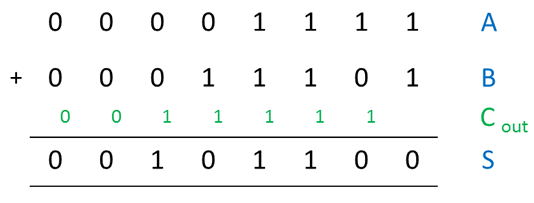
To add two multi-bit numbers together, we add pairs of bits together.
When we add a pair of bits together we generate a sum, which we will call S, and a carry bit of either 1 or 0 (0 if there is no carry), which we will call Cout.
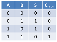
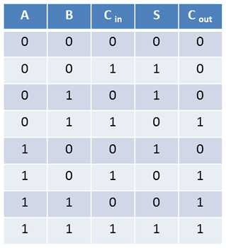
The possibilities when adding together just a pair of bits A and B are described in this truth table.
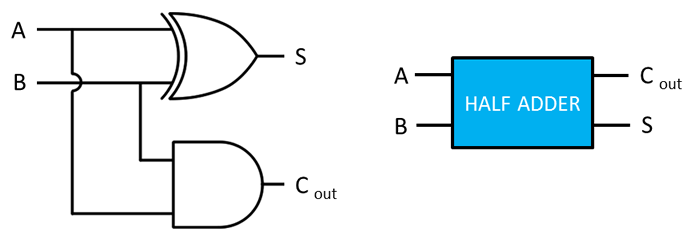
Half adder circuit
The HALF ADDER circuit can add two bits together as described in the truth table above. It combines an XOR gate with an AND gate. Notice that the output in column S of the truth table is that of an XOR gate, while the output in column C out is that of an AND gate.
Full adder circuit
When adding together a pair of bits A and B, we may also need to add in an extra bit that was generated as a carry out when the previous pair of bits were added together. This means we actually need THREE inputs for each pair of bits, namely A, B and Cin. This truth table describes the operation more correctly.
A circuit described by this truth table can be created by combining two half adders and an OR gate as shown below. This combination is called a FULL ADDER.
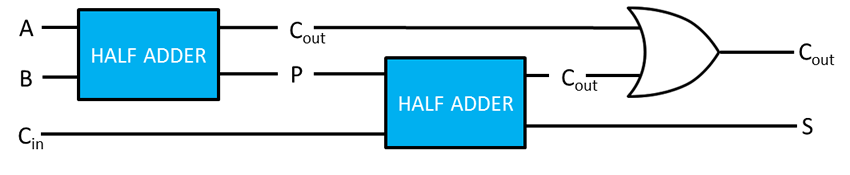
So how does the full adder work? Consider how you would add 2+3+4. You first add 2+3 to generate a partial result of 5 which you then add to 4 in order to get 9. The operation of the full adder is similar.
Here, the first half adder adds A and B to produce a partial result P. This is then added to Cin by the second half adder. Each half adder may generate a new carry bit Cout. The OR gate allows a carry out generated by either half adder to be passed on.
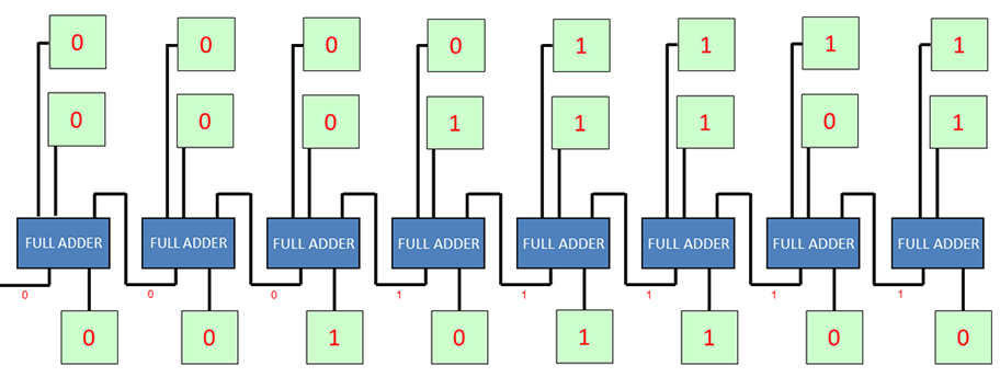
Ripple carry adder
Full adders can be daisy chained to make a circuit that will add together a pair of multi-bit binary numbers. This circuit is known as a ripple carry adder and can be found in the Arithmetic and Logic Unit of the CPU.