
Logic gates can be combined together to produce useful circuits and a combination of logic gates can be described by means of a truth table.
Example 1
Here you can see a combination of two AND gates and a NOT gate. The inputs are labelled A and B and the ultimate output is E. You can see that some intermediate positions, C and D, have also been labelled.
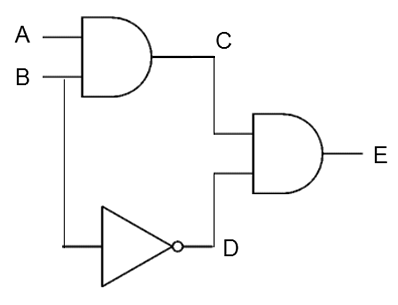
Here is a truth table for this combination of gates indicating the output, and the intermediate values C and D, for each combination of input values.
| A | B | C | D | E |
| 0 | 0 | 0 | 1 | 0 |
| 0 | 1 | 0 | 0 | 0 |
| 1 | 0 | 0 | 1 | 0 |
| 1 | 1 | 1 | 0 | 0 |
Example 2
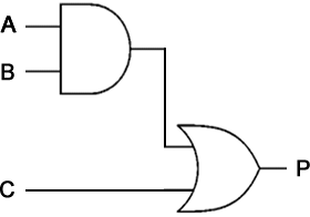
This gate combination has three inputs. Every combination of inputs is included in this truth table. Although no intermediate values are included, you would have to work these out anyway in order to arrive at the output.
| A | B | C | P |
| 0 | 0 | 0 | 0 |
| 0 | 0 | 1 | 1 |
| 0 | 1 | 0 | 0 |
| 0 | 1 | 1 | 1 |
| 1 | 0 | 0 | 0 |
| 1 | 0 | 1 | 1 |
| 1 | 1 | 0 | 1 |
| 1 | 1 | 1 | 1 |
NOTE:
With 3 inputs, there are 23 = 8 possible combinations of input values. It is conventional to list these in the truth table in ascending numerical order (binary zero, 000, at the top and binary seven, 111, at the bottom).
Example 3
In this example we have four possible inputs.
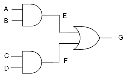
Try this – Create a truth table for the combination of logic gates shown above. Include all combinations of inputs and show values at E, F and G for each possible combination.