
Building blocks
Transistors and resistors are electronic components that for the basis of most computer circuitry, albeit in miniaturized form, in their millions, on silicon chips. Transistors and resistors can be combined in various ways to create special circuits known as logic gates. Logic gates are the fundamental building blocks of computer electronics. Logic gates are simple electronic circuits that can manipulate electrical voltages, producing different outputs (high or low) depending on their inputs (high or low). You need to be aware of the significance of logic gates in digital computing. You need to know the names of the four main gates, NOT, AND, OR and XOR, and be able to draw a truth table for each.
NOT
A NOT gate can be made with one transistor and two resistors, so it is very simple. It has one input and one output. what is special about a NOT gate is that if a voltage is applied to the input, there is no voltage at the output. Conversely, if there is no voltage at the input, there will be a voltage at the output. In other words, if a 1 goes in, a 0 comes out, and if a 0 goes in, a 1 comes out. The NOT gate circuit is represented with the following symbol:
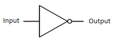
The truth table for a NOT gate is very simple because there are only two possible values for the input, 1 and 0. The output of a NOT gate is the inverse of the input, which is why the NOT gate is sometime called an ‘inverter’.
| Input 1 | Output |
| 0 | 1 |
| 1 | 0 |
AND
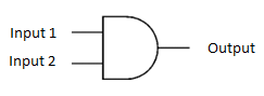
An AND gate can be made from two transistors and three resistors. The AND gate has two inputs and one output. If both of the inputs for an AND gate are 1, the output is 1. If either or both inputs are 0, the output will be 0. The AND gate circuit is represented with the following symbol:
Here is the truth table for an AND gate:
| Input 1 | Input 2 | Output |
| 0 | 0 | 0 |
| 0 | 1 | 0 |
| 1 | 0 | 0 |
| 1 | 1 | 1 |
NOTE:
It is conventional to list the input combinations in a truth table in ascending numerical order. As you can see in the table above, binary zero (00) is at the top, followed by one (01), then two (10), then three (11).
OR
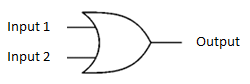
An OR gate can be made from two transistors and three resistors, wired in a slightly different way to an AND gate. The OR gate also has two inputs and one output. If either of the inputs, or both of the inputs, is 1, the output is 1. If both inputs are 0, the output will be 0. The OR gate circuit is represented with the following symbol:
Here is the truth table for an OR gate:
| Input 1 | Input 2 | Output |
| 0 | 0 | 0 |
| 0 | 1 | 1 |
| 1 | 0 | 1 |
| 1 | 1 | 1 |
XOR
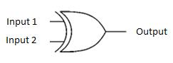
An XOR gate can be made with a combination of the other three gates. Like this:

XOR stands for eXclusive OR. The XOR gate has two inputs and one output. It is similar to the OR gate in that if either of the inputs is 1, the output is 1, but if both the inputs are 1, the output will be 0. The XOR gate circuit is represented with the following symbol:
Here is the truth table for an XOR gate:
| Input 1 | Input 2 | Output |
| 0 | 0 | 0 |
| 0 | 1 | 1 |
| 1 | 0 | 1 |
| 1 | 1 | 0 |